 English
  Русский
Sensor
Dieser Post ist auch verfügbar auf: Russian
Sensor part for Multitouch sperical surface
| During the research stage of the development of the hemispherical surface of large diameter our team studied existing multi-touch technologies. The comparison table was set up to simplify the decision. This table compares all known multi-touch technologies based on the following criteria: • Multi-touch • Surface Size • Curvature (sphere) of the surface • Transmittance / optics of surface • All-in installation • Sensitivity to ambient lighting conditions • Sensitivity to vibrationThe first group of the reviewed technologies failed to solve problems on a spherical surface (e.g.: SAW – Surface Acoustic Wave and infrared-frame, resistive and surface capacitive solutions).The second group consists of technologies that do not allow a solution that preserves the transparency of the screen, such as: “in cell”-resistive and “in cell”-infrared.The third group includes technologies that require installation of additional equipment into the room (e.g.: video cameras, reflectors, gloves, pins or sensors). |

Capacitive multi-touch solution |
| A separate explanation is in order to explain the reasons for rejecting approach taken by Microsoft in designing their Kinect device. Kinect uses near-infrared transmitter to create a pattern of near-infrared dots. The distortion of this pattern and measurement of time it takes to reflect each ray from the objects in space allows creating a precise depth map of the space in front of the camera. The changes to the map are updated 30 times per second and allow precise movement detection, face recognition, and feature extraction. It is important here to specify what “precise” means in the preceding description. Kinect is able to “see” object 1.2-3.5 meters from the camera, with limited perception in the range of 0.7 to 6 meters. The view is 57º horizontally and 43º vertically. The depth map is accurate to about 1cm. These measurements clearly show that the motion and gesture detection using Kinect simply would not work on a surface of a spherical screen as the precision is not high enough and the view of the camera is too narrow for a half-sphere screen. |

Multi-touch solution based on with Microsoft Kinect |
Thus, there remained only two approaches:
1. Projective Infrared – with the sources and detectors of infrared radiation located inside of the spherical screen surface.
| This solution has several disadvantages: • Sensitivity to vibration. • Sensitivity to direct sunlight, which negatively affects the quality and functionality of the system. This, for example, prevents using this approach in the open space that is not protected from direct and reflected sunlight in the room. • Sensitivity to reflected sunlight. • Sensitivity to changes in lighting of the room (e.g.: turning the light on or off). • Failures with screen surface contamination. |

Infrared multitouch |
2. Projective-capacitive (PCT) – the sensors are laid on the inner side of the surface in a form of a grid of electrodes (and possibly just wires).
| The coordinates of a point are calculated by measuring changes in capacitance caused by the finger touching the surface.
To implement this approach, one first needs to find a way or to develop a technology that enables laying of the conductors (wires) inside a spherical surface. When “bubbling” (inflation) is used to create a spherical surface out of a flat one – all the wires tear because of the tension. |

Projective capasitive solution Grid with gluing wires |

Since the capacitive solution was not developed in the scheduled project time frame, the infrared solution was implemented.
Infrared solution installed on the GLOBE
| The essence of this solution is that multiple sources of infrared light are installed behind the screen surface, i.e. inside the cabinet. These sources are purposefully designed to cover the inner surface of the screen and user’s fingers reflect this radiation into the interior. Infrared cameras (similar to night vision devices) can be used as the sensors (receivers). One cannot use a single camera due to its range of view, but two cameras cover (i.e. see) the entire inner surface of GLOBE (our screen). Because the depth of the cabinet was limited to 25 cm, in our case it was not enough to use a simple short-focus camera. As in the case with the projector, special optics had to be used to solve the problem. Since more than one camera was used, it was necessary to develop a software program that would stitch (combine) images generated by each camera into one. Additionally, a calibration program was needed to map coordinates of the stitched camera image to the coordinates of the image visible on the screen.One of the main software components is the TRACKER, which keeps track of the coordinates of the points of contact within the surface, and, most importantly, determines whether each touch is a new one or a part of an unbroken line.Finally, a component was used to transfer multi-touch coordinates and gesture types to the operating system (Windows 7). |

Infrared solution for the GLOBE |
Capacitive multi-touch screens for hemispherical display
Shortcomings of infrared solutions were known from the start and it was, therefore, decided to find a suitable projective-capacitive solution.
Finding such a solution required solving two problems simultaneously:
1. Develop technology for bonding of copper (or other) very thin wires inside of the hemisphere.
We further call this sub-problem “PCT-screen.”
2. Develop technology that allows receiving information about changes in the capacitive characteristics at the points of the finger contact, taking into account the extremely large screen (about 2 meters).
We further call this sub-problem “PCT-controller”.
Multitouch PCT Solution: Prototype from first System integrator
| At this stage of the study, a young startup was found, which attempted to tackle these problems. They had successfully developed a prototype – a hemisphere of about 40 cm in diameter. The results were more than convincing!But, that was where the success was over. |

PCT multitouch prototype |
Attempts to obtain a stable signal and calculate the coordinates of the touch on a flat-screen (1.40m x 1.40m with 7 mm increment between the wires) culminated in a failure. The screen acted as an antenna and the noise was so great, that the signal at the site of contact could not be determined.
Attempts to resolve the problem by doubling the pitch from 7 mm to 14 mm between the wires failed.
In parallel, the Portuguese attempted to create a robot that was able to lay the wires down and glue them to the inner surface of the hemisphere. And it appeared promising at first. A few rows of copper wire were laid down and glued in place. Further advances in this direction were not forthcoming.

Surface with gluing wires: bad quality |
In all likelihood, the following problems remained unresolved:
1. Making sure the rows were parallel to each other.
2. It was not possible to lay all 128 rows of wire down and glue them in time before the glue began to harden.
The glue had to be sprayed again.
Fresh glue dissolved the hardened glue and the wires already glued on peeled.
3. For the same reason it was not possible to lay the perpendicular rows of wire down, as they dissolved the glue of the lower layers.
4. Glue could not be applied evenly, so there were visible stains.
Thus, the screen lost some of its picture resolution.
Surface with gluing wires: bad quality |
As soon as the problems became obvious, a renewed search for a firm that could solve the problem had to be started. And such a company was found in Estonia – the country which gave Skype to mankind.
Estonian solutions for Capacitive multitouch sperical screen
To begin, a search for a suitable adhesive was undertaken. In addition to the optical properties, special attention was focused on making sure the next layer of glue does not dissolve the previous one. Once the glue has been selected, the baton passed to the Mechanical Engineers.
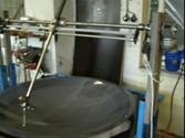
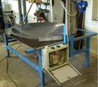
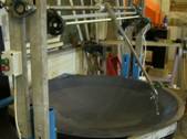
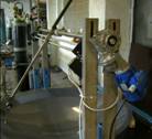
They created a semi-automatic system (not all processes were automatable) for laying and gluing thin wire. This equipment is sufficiently generic to be able to lay the wire down and glue it to hemispheres of up to 3 meters in diameter!
 |
 |
 |
 |
|
Robot for laying and gluing thin wire |
|||
At this time the following problems had been resolved:
1. Absolutely parallel rows.
Minimal step: 1 mm.
Thus, depending on need, parallel conductors can be attached at one or more millimeters.
2. Ensuring continuity and straightness of pasted conductors.
Continuity and straightness of pasted conductor was made possible by an innovative device for feeding the wire and for providing sufficient time for the bonding process, allowing the surface to “grab” the wire and, thus, to assure that it does not come off, despite the force of the tension.
3. Avoiding mechanical damages during laying the wire down and bonding.
When excessive force for clamping the wire to the surface is applied when gluing the first layer or the second perpendicular one, there is a risk of damage of the surface of the sphere and the previously deposited conductors.
This problem was solved by careful selection of the clipping material and its geometry.

Domed surface: backside with wires and electronic |

Domed surface: backside with wires |
Estonian solutions for Capacitive multitouch: controller
A grid consisting of 128 lines of vertical resolution and of 128 lines of horizontal resolution was implemented to obtain a satisfactory resolution, taking into account the screen size (1 m in diameter).
This corresponded to a step around 7.8 millimeters.
It was clear from the beginning that the classical projective capacitive (PCT) approach was not suitable, because the screen was too large. Therefore, the Estonian company founded by former members of the Estonian Academy of Sciences and scientists from Tallinn Technical University used a different approach.
A 128×128 grid on the inner surface of the hemisphere produced 16,384 cells. Thus, the problem was reduced to determining the presence or absence of contact in each of the cells. This was done by measuring the changes in the signal of each cell. Modern literature calls this approach digital capacitive.
Professionals would understand that a reference signal had to be properly selected and special digital processing algorithms had to be applied to filter the noise from the signal to accurately detect touch.
 |
 |
|
|
Projective capacitive digital multi-touch solution |
||